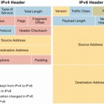
What is CEF?
Definition from Cisco.com :
Cisco Express Forwarding (CEF) is advanced, Layer 3 IP switching technology. CEF optimizes network performance and scalability for networks with large and dynamic traffic patterns, such as the Internet, on networks characterized by intensive Web-based applications, or interactive sessions.
To understand this better, one has to understand why and how CEF came about. With Cisco IOS there are different Switching Methods, that define how packets are forwarded through a router. The first method, which happens to be the oldest and slowest is Process-Switching. Alternatively when packets arrive, the interface processor can interrupt the central CPU and asks it to switch the packet according to a route cache or switching table. That cache or table can be built in several ways, the two of interest here are Fast-Switching and CEF.
With Process-Switching, when a packet enters the router the Layer-2 info is stripped off, the packet is then copied to the CPU memory where a L3 lookup is performed, and any other CPU required features, like NAT, queuing, compression etc, along with any other housekeeping like lowering the TTL, recalculating the CRC are done, before the frame is rewritten with the new L2 destination address and sent to the outgoing interface. The Big, the Bad and the Ugly!
With Fast-Switching, the first packet in a flow is still copied to the CPU for the L3 lookup and housekeeping, before being rewritten with the L2 destination address. The switching of the first packet by the central CPU gives the CPU the opportunity to build a cache called the fast-switching cache ‘Route Caching’ , which is used to switch all subsequent packets for the same destination using the same switching path across the router. With Fast-Switching the cache is only built on demand, which can be time consuming when huge numbers of potential destinations are involved. To avoid this a pre-build cache was needed, and thus CEF was born.
Route Caching is now been referred as Demand-Base
With CEF (Cisco Express Forwarding), there are two main data structures under now a Topology Base concept:
- The Adjacency-Table : is responsible for the MAC or Layer 2 rewrite. This adjacency can be built from ATM, Frame Relay map statements, dynamic information learned from Ethernet-ARP, inverse ARP on ATM, or Frame Relay. The Layer 2 rewrite string contains the new Layer 2 header which is used on the forwarded frame. For Ethernet, this is the new destination and source MAC address and the Ethertype. For PPP, the Layer 2 header is the complete PPP header, including the Layer 3 protocol ID.
- FIB (Forwarding Information Base) Table : The CEF table/FIB table holds the essential information, taken from the ‘RIB’ routing Information Base, to be able to make a forwarding decision for a received IP packet. This information includes the IP prefix, the recursively evaluated next hop, and the outgoing interface.
PROCESS SWITCHING:
How The router Process the packet :
The router remove the header ( Layer 2 ) from the incoming packet
The router examine the layer 3 addressing and take a decision how to forward the packet .
The layer 2 is then rewritten , which could mean changing the source and destination mac address computing cycle redundancy check ( CRC )
Then the packet is forwarded to the right interface.
The inconvenient is that the 1st packet must always use Process Switching.
Process Switching involve direct CPU process … in another word : router configured for process switching can suffer significantly.
To configure an interface for Process Switching you need to disable Fast Switching on that interface
no ip route-cache
FAST SWITCHING :
Fast Switching use the router cache maintain by the router data plane.
How The router Process the packet :
The 1st packet in a data flow is process by the cpu
The router determine how to forward the 1st frame of data flow from the router fast cache information .
Future packets with the same destination address that match the cache entry will be forward right away.
Fast Switching is also referred ” Route once, forward many times”.
Fast Switching can reduce a router Cpu utilization compare to Process Switching.
To configure Fast Switching is can be configure on the interface by using :
ip route-cache
CISCO EXPRESS FORWARDING ( CEF )
The CEF process flow:
When a packet enters the router, the router strips off the Layer 2 information.
The router looks up the destination IP address in the CEF table (FIB), and it makes a forwarding decision.
The result of this forwarding decision points to one adjacency entry in the adjacency table.
The information retrieved from the adjacency table is the Layer 2 rewrite string, which enables the router to put a new Layer 2 header onto the frame,
The packet is switched out onto the outgoing interface toward the next hop.
CEF is enable by default on most routers if not we can enable it by default using the command : ip cef
you can enable it on a interface base by using the command : ip route-cache cef
Another Example from Cisco Web Site Document # 13706 :
http://www.cisco.com/c/en/us/support/docs/ip/express-forwarding-cef/13706-20.html
Introduction
There are a plethora of switching paths available to various Cisco routers and Cisco IOS® releases. Which is the best one for your network, and how do they all work? This white paper is an attempt to explain each of the following switching paths so you can make the best decision about which switching path fits your network.
First, examine the forwarding process itself. There are three steps to forwarding a packet through a router:
- Determine if the packet’s destination is reachable.
- Determine the next hop toward the destination, and the interface through which that next hop is reachable.
- Rewrite the Media Access Control (MAC) header on the packet so it will successfully reach its next hop.
Each of these steps is critical for the packet to reach its destination.
Note: Throughout this document, the IP switching path is used as an example; virtually all the information provided here is applicable to equivalent switching paths for other protocols, if they exist.
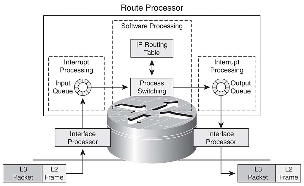
Process Switching
Process switching is the lowest common denominator in switching paths; it is available on every version of IOS, on every platform, and for every type of traffic being switched. Process switching is defined by two essential concepts:
- The forwarding decision and information used to rewrite the MAC header on the packet are taken from the routing table (from the routing information base, or RIB) and the Address Resolution Protocol (ARP) cache, or from some other table that contains the MAC header information mapped to the IP address of each host that is directly connected to the router.
- The packet is switched by a normal process running within IOS. In other words, the forwarding decision is made by a process scheduled through the IOS scheduler and running as a peer to other processes on the router, such as routing protocols. Processes that normally run on the router are not interrupted to process switch a packet.
The figure below illustrates the process switching path.
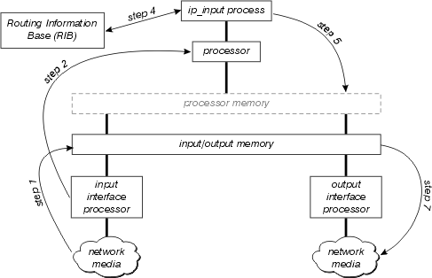
Examine this diagram in more detail:
- The interface processor first detects there is a packet on the network media, and transfers this packet to the input/output memory on the router.
- The interface processor generates a receive interrupt. During this interrupt, the central processor determines what type of packet this is (assume it is an IP packet), and copies it into processor memory if necessary (this decision is platform dependent). Finally, the processor places the packet on the appropriate process’ input queue and the interrupt is released.
- The next time the scheduler runs, it notes the packet in the input queue of ip_input, and schedules this process to run.
- When ip_input runs, it consults the RIB to determine the next hop and the output interface, then consults the ARP cache to determine the correct physical layer address for this next hop.
- ip_input then rewrites the packet’s MAC header, and places the packet on the output queue of the correct outbound interface.
- The packet is copied from the output queue of the outbound interface to the transmit queue of the outbound interface; any outbound quality of service takes place between these two queues.
- The output interface processor detects the packet on its transmit queue, and transfers the packet onto the network media.
Almost all features that effect packet switching, such as Network Address Translation (NAT) and Policy Routing, make their debut in the process switching path. Once they have been proven, and optimized, these features might, or might not, appear in interrupt context switching.
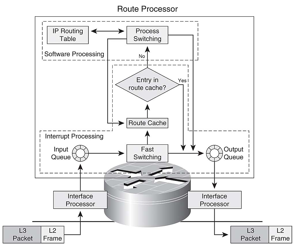
Interrupt Context Switching
Interrupt context switching is the second of the primary switching methods used by Cisco routers. The primary differences between interrupt context switching and process switching are:
- The process currently running on the processor is interrupted to switch the packet. Packets are switched on demand, rather than switched only when the ip_input process can be scheduled.
- The processor uses some form of route cache to find all the information needed to switch the packet.
This figure illustrates interrupt context switching:
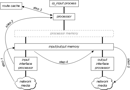
Examine this diagram in more detail:
- The interface processor first detects there is a packet on the network media, and transfers this packet to the input/output memory on the router.
- The interface processor generates a receive interrupt. During this interrupt, the central processor determines what type of packet this is (assume it is an IP packet), and then begins to switch the packet.
- The processor searches the route cache to determine if the packet’s destination is reachable, what the output interface should be, what the next hop towards this destination is, and finally, what MAC header the packet should have to successfully reach the next hop. The processor uses this information to rewrite the packet’s MAC header.
- The packet is now copied to either the transmit or output queue of the outbound interface (depending on various factors). The receive interrupt now returns, and the process that was running on the processor before the interrupt occurred continues running.
- The output interface processor detects the packet on its transmit queue, and transfers the packet onto the network media.
The first question that comes to mind after reading this description is “What is in the cache?” There are three possible answers, depending on the type of interrupt context switching:
Fast Switching
Fast switching stores the forwarding information and MAC header rewrite string using a binary tree for quick lookup and reference. This figure illustrates a binary tree:
In Fast Switching, the reachability information is indicated by the existence of a node on the binary tree for the destination of the packet. The MAC header and outbound interface for each destination are stored as part of the node’s information within the tree. The binary tree can actually have 32 levels (the tree above is extremely abbreviated for the purpose of illustration).
In order to search a binary tree, you simply start from the left (with the most significant digit) in the (binary) number you are looking for, and branch right or left in the tree based on that number. For instance, if you are looking for the information related to the number 4 in this tree, you would begin by branching right, because the first binary digit is 1. You would follow the tree down, comparing the next digit in the (binary) number, until you reach the end.
Characteristics of the Fast Switching
Fast Switching has several characteristics that are a result of the binary tree structure and the storage of the MAC header rewrite information as part of the tree nodes.
- Because there is no correlation between the routing table and the fast cache contents (MAC header rewrite, for example), building cache entries involves all the processing that must be done in the process switching path. Therefore, fast cache entries are built as packets are process switched.
- Because there is no correlation between the MAC headers (used for rewrites) in the ARP cache and the structure of the fast cache, when the ARP table changes, some portion of the fast cache must be invalidated (and recreated through the process switching of packets).
- The fast cache can only build entries at one depth (one prefix length) for any particular destination within the routing table.
- There is no way to point from one entry to another within the fast cache (the MAC header and outbound interface information are expected to be within the node), so all routing recursions must be resolved while a fast cache entry is being built. In other words, recursive routes cannot be resolved within the fast cache itself.
Aging Fast Switching Entries
In order to keep the fast switching entries from losing their synchronization with the routing table and ARP cache, and to keep unused entries in the fast cache from unduly consuming memory on the router, 1/20th of the fast cache is invalidated, randomly, every minute. If the routers memory drops below a very low watermark, 1/5th of the fast cache entries are invalidated every minute.
Fast Switching Prefix Length
What prefix length does the fast switching build entries for if it can only build to one prefix length for every destination? Within the terms of the fast switching, a destination is a single reachable destination within the routing table, or a major network. The rules for deciding what prefix length to build a given cache entry are:
- If building a fast policy entry, always cache to /32.
- If building an entry against an Multiprotocol over ATM virtual circuit (MPOA VC), always cache to /32.
- If the network is not subnetted (it is a major network entry):
- If it is directly connected, use /32;
- Otherwise use the major net mask.
- If it is a supernet use the supernet’s mask.
- If the network is subnetted:
- If directly connected, use /32;
- If there are multiple paths to this subnet, use /32;
- In all other cases, use longest prefix length in this major net.
Load Sharing
Fast switching is entirely destination based; load sharing occurs on a per-destination basis. If there are multiple equal cost paths for a particular destination network, fast cache has one entry for each host reachable within that network, but all traffic destined to a particular host follows one link.
Optimum Switching
Optimum switching stores the forwarding information and the MAC header rewrite information in a 256 way multiway tree (256 way mtree). Using an mtree reduces the number of steps which must be taken when looking up a prefix, as illustrated in the next figure.
Each octet is used to determine which of the 256 branches to take at each level of the tree, which means there are, at most, 4 lookups involved in finding any destination. For shorter prefix lengths, only one-three lookups may be required. The MAC header rewrite and output interface information are stored as part of the tree node, so cache invalidation and aging still occur as in the fast switching.
Optimum Switching also determines the prefix length for each cache entry in the same way as fast switching.
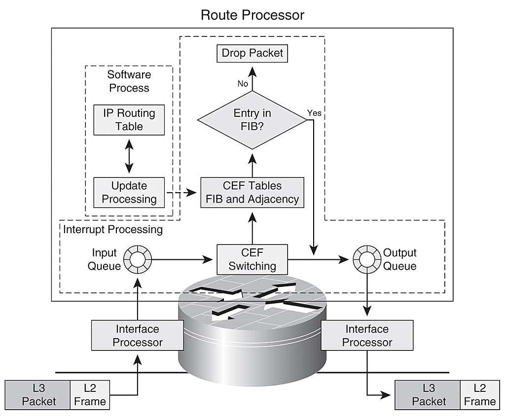
Cisco Express Forwarding
Cisco Express Forwarding, also uses a 256 way data structure to store forwarding and MAC header rewrite information, but it does not use a tree. Cisco Express Forwarding uses a trie, which means the actual information being searched for is not in the data structure; instead, the data is stored in a separate data structure, and the trie simply points to it. In other words, rather than storing the outbound interface and MAC header rewrite within the tree itself, Cisco Express Forwarding stores this information in a separate data structure called the adjacency table.
This separation of the reachability information (in the Cisco Express Forwarding table) and the forwarding information (in the adjacency table), provides a number of benefits:
- The adjacency table can be built separately from the Cisco Express Forwarding table, allowing both to build without process switching any packets.
- The MAC header rewrite used to forward a packet is not stored in cache entries, so changes in a MAC header rewrite string do not require invalidation of cache entries.
- You can point directly to the forwarding information, rather than to the recursed next hop, in order to resolve recursive routes.
Essentially, all cache aging is eliminated, and the cache is pre-built based on the information contained in the routing table and ARP cache. There is no need to process switch any packet to build a cache entry.
Other Entries in the Adjacency Table
The adjacency table can contain entries other than MAC header rewrite strings and outbound interface information. Some of the various types of entries that can be placed in the adjacency table include:
- cache—A MAC header rewrite string and outbound interface used to reach a particular adjacent host or router.
- receive—Packets destined to this IP address should be received by the router. This includes broadcast addresses and addresses configured on the router itself.
- drop—Packets destined to this IP address should be dropped. This could be used for traffic denied by an access list, or routed to a NULL interface.
- punt—Cisco Express Forwarding cannot switch this packet; pass it to the next best switching method (generally fast switching) for processing.
- glean—The next hop is directly attached, but there are no MAC header rewrite strings currently available.
Glean Adjacencies
A glean adjacency entry indicates that a particular next hop should be directly connected, but there is no MAC header rewrite information available. How do these get built and used? A router running Cisco Express Forwarding and attached to a broadcast network, as shown in the figure below, builds a number of adjacency table entries by default.

The four adjacency table entries built by default are:
10.1.1.0/24, version 17, attached, connected
0 packets, 0 bytes
  via Ethernet2/0, 0 dependencies
    valid glean adjacency
10.1.1.0/32, version 4, receive
10.1.1.1/32, version 3, receive
10.1.1.255/32, version 5, receive
Note there are four entries: three receives, and one glean. Each receive entry represents a broadcast address or an address configured on the router, while the glean entry represents the remainder of the address space on the attached network. If a packet is received for host 10.1.1.50, the router attempts to switch it, and finds it resolved to this glean adjacency. Cisco Express Forwarding then signals that an ARP cache entry is needed for 10.1.1.50, the ARP process sends an ARP packet, and the appropriate adjacency table entry is built from the new ARP cache information. After this step is complete, the adjacency table has an entry for 10.1.1.50.
10.1.1.0/24, version 17, attached, connected
0 packets, 0 bytes
  via Ethernet2/0, 0 dependencies
    valid glean adjacency
10.1.1.0/32, version 4, receive
10.1.1.1/32, version 3, receive
10.1.1.50/32, version 12, cached adjacency 208.0.3.2
0 packets, 0 bytes
  via 208.0.3.2, Ethernet2/0, 1 dependency
    next hop 208.0.3.2, Ethernet2/0
    valid cached adjacency
10.1.1.255/32, version 5, receive
The next packet the router receives destined for 10.1.1.50 is switched through this new adjacency.
Load Sharing
Cisco Express Forwarding also takes advantage of the separation between the Cisco Express Forwarding table and the adjacency table to provide a better form of load sharing than any other interrupt context switching mode. A loadshare table is inserted between the Cisco Express Forwarding table and the adjacency table, as illustrated in this figure:
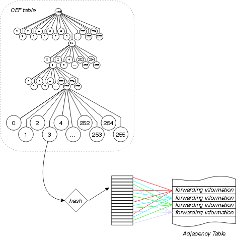
The Cisco Express Forwarding table points to this loadshare table, which contains pointers to the various adjacency table entries for available parallel paths. The source and destination addresses are passed through a hash algorithm to determine which loadshare table entry to use for each packet. Per packet load sharing can be configured, in which case each packet uses a different loadshare table entry.
Each loadshare table has 16 entries among which the paths available are divided based on the traffic share counter in the routing table. If the traffic share counters in the routing table are all 1 (as in the case of multiple equal cost paths), each possible next hop receives an equal number of pointers from the loadshare table. If the number of available paths is not evenly divisible into 16 (since there are 16 loadshare table entries), some paths will have more entries than others.
Beginning in Cisco IOS Software Release 12.0, the number of entries in the loadshare table is reduced to make certain each path has a proportionate number of loadshare table entries. For instance, if there are three equal cost paths in the routing table, only 15 loadshare table entries are used.