Installation
This section provides information about how to install your FortiGate and use it in your network, after you have finished the initial set-up outlined in the FortiGate model’s QuickStart Guide. The section also provides troubleshooting methods to use if the FortiGate does not function as desired after completing the installation.
The following topics are included in this section:
NAT/Route Mode vs Transparent Mode
A FortiGate unit can operate in one of two modes: NAT/Route or Transparent.
NAT/Route mode is the most common operating mode. In this mode, a FortiGate unit is installed as a gateway or router between two networks. In most cases, it is used between a private network and the Internet. This allows the FortiGate to hide the IP addresses of the private network using network address translation (NAT). NAT/Route mode is also used when two or more Internet service providers (ISPs) will be used to provide the FortiGate with redundant Internet connections.
A FortiGate unit in Transparent mode is installed between the internal network and the router. In this mode, the FortiGate does not make any changes to IP addresses and only applies security scanning to traffic. When a FortiGate is added to a network in Transparent mode, no network changes are required, except to provide the FortiGate with a management IP address. Transparent mode is used primarily when there is a need to increase network protection but changing the configuration of the network itself is impractical.
Installing a FortiGate in NAT/Route Mode
There are two main types of FortiGate installations using NAT/Route mode: standard installations that receive Internet access from a single Internet service provider (ISP) and installations that have two or more ISPs for redundant Internet connections. For both installations, the first step is to select which internal Switch mode you require your FortiGate to operate in.
Selecting an Internal Switch mode
The internal Switch mode determines how the FortiGate’s physical ports are managed by the FortiGate. The two main modes are Switch mode and Interface mode.
Switch mode vs Interface mode
In Switch mode, all of the internal interfaces are part of the same subnet and treated as a single interface, which is called either lan or internal by default, depending on the FortiGate model. Switch mode is commonly used in settings where the network layout is fairly basic, with most users being on the same subnet.
In Interface mode, the physical interfaces of the FortiGate unit are configured and handled individually, with each interface having its own IP address. Interfaces can be logically or virtually combined by configuring them as part of either hardware or software switches (for more information, see Hardware Switches vs Software Switches), which allow multiple interfaces to be treated as a single interface. FortiGate units that are in Interface mode by default start with a hardware switch called either lan or internal, depending on the FortiGate model. This mode is designed for complex networks where different subnets are used to compartmentalize the network traffic.
The default mode that a FortiGate starts in varies depending on the model. Switch mode has been the most common factory default setting; however, the number of models that have Interface mode as their default setting is increasing.
In order to determine which mode your FortiGate unit is in, go to System > Network > Interfaces. Locate the interface called either lan or internal, which all FortiGate units have be default. If the interface is listed as a physical interface in the Type column, then your FortiGate is in Switch mode. If the interface is a hardware switch, then your FortiGate is in Interface mode.
You can also determine what mode your FortiGate is by going to System > Dashboard > Status and enter either of the following commands into the CLI Console: config system global show. In the output that is displayed after you hit the Enter key, find the line that begins with set internal-switch-mode. This will tell you which mode your FortiGate is currently in.
If you need to change the mode your FortiGate unit is in, go to System > Dashboard > Status and enter either of the following commands into the CLI Console:
| Before switching modes, you must make sure that none of the physical ports that make up the lan or internal interface are referenced in the FortiGate configuration. |
- Command to change the FortiGate to Switch mode:
config system global
set internal-switch-mode switch
end
- Command to change the FortiGate to Interface modeHub mode:
config system global
set internal-switch-mode interface
end
| There is a third mode, called Hub mode, that is available on some FortiGate models. Hub mode is similar to Switch mode, except the network device that it is emulating is a Layer 2 device instead of Layer 3. In Hub mode, he interfaces do not learn the MAC addresses of the devices on the network they are connected to and may also respond quicker to network changes in some circumstances.
You should only select Hub mode if you are having network performance issues when operating with Switch mode. The configuration of the FortiGate unit is the same whether in Switch mode or Hub mode. |
Hardware Switches vs Software Switches
Both hardware and software switches are used to to allow ports to be grouped together and treated as a single interface. The main difference between the two types of switches is that hardware switches use the underlying switch chip/driver to handle all of the switching directly, while software switches do this in the FortiOS software.
The two types of switches also have differences in which commands and features are available, which vary depending on your FortiGate’s model. In most situations, using a hardware switch is preferred for better performance, with software switches used in cases where a feature is required that is unavailable for a hardware switch.
For more information about creating hardware and software switches, please refer to the System Administration handbook.
Standard Installation in NAT/Route Mode
Network with a FortiGate unit in NAT/Route mode and a single ISP
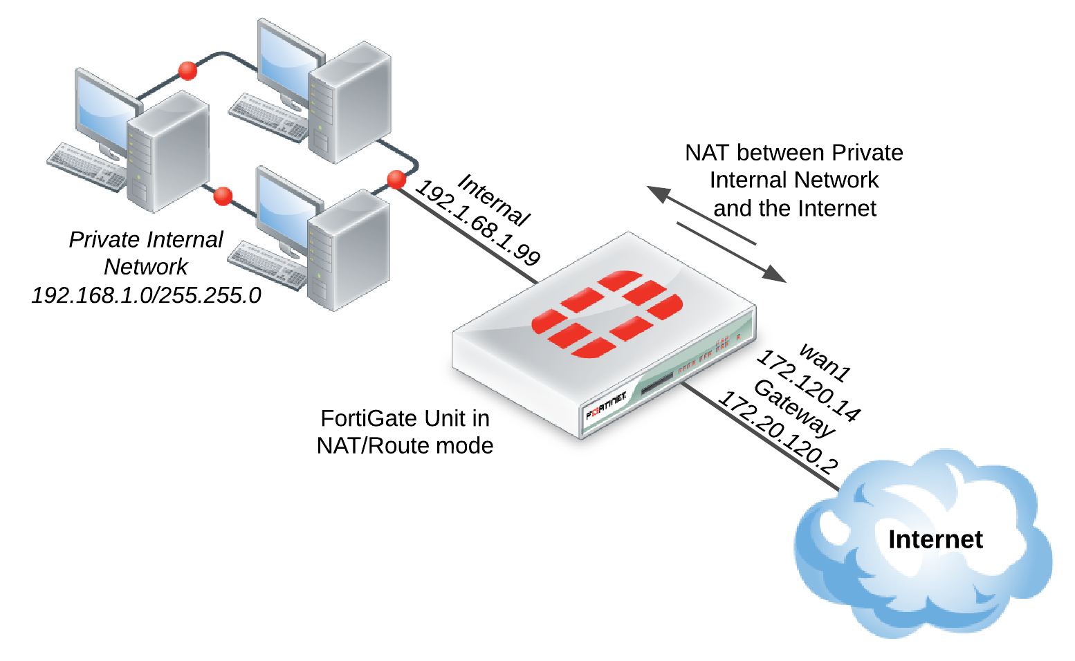
- Connect the FortiGate’s Internet-facing interface (typically WAN1) to your ISP-supplied equipment.
- Connect a PC to the FortiGate using an internal port (typically port 1).
- Power on the ISP’s equipment, the FortiGate unit, and the PC on the internal network.
- From the PC on the internal network, connect to the FortiGate’s web-based manager using either FortiExplorer or an Internet browser (for information about connecting to the web-based manager, please see your models QuickStart Guide). Login using an admin account (the default admin account has the username
adminand no password). - Go to System > Network > Interfaces and edit the Internet-facing interface. Set Addressing Mode to Manual and the IP/Netmask to your public IP address. Select OK.
- Edit the internal interface. Set Addressing Mode to Manual and set the IP/Netmask to the private IP address you wish to use for the FortiGate. Select OK.
- Go to Router > Static > Static Routes (or System > Network > Routing, depending on your FortiGate model) and select Create New to add a default route. Set the Destination IP/Mask to 0.0.0.0/0.0.0.0, the Device to the Internet-facing interface, and the Gateway to the gateway (or default route) provided by your ISP or to the next hop router, depending on your network requirements. Select OK.
| A default route always has a Destination IP/Mask of 0.0.0.0/0.0.0.0. Normally, you would have only one default route. If the static route list already contains a default route, you can either edit it or delete it and add a new one. |
- (Optional) The FortiGate unit’s DNS Settings are set to use FortiGuard DNS servers by default, which is sufficient for most networks. However, if you need to change the DNS servers, go to System > Network > DNS and add Primary and Secondary DNS servers. Select Apply.
- If your network uses IPv4 addresses, go to Policy & Objects > Policy > IPv4 and select Create New to add a security policy that allows users on the private network to access the Internet.
| Some FortiGate models include the IPv4 security policy in the default configuration. If you have one of these models, this step has already been done for you and as soon as your FortiGate unit is connected and the computers on your internal network are configured, users should be able to access the Internet. |
If your network uses IPv6 addresses, go to Policy & Objects > Policy > IPv6 and select Create New to add a security policy that allows users on the private network to access the Internet. If the IPv6 menu option is not available, go to System > Config > Features, turn on IPv6, and select Apply. For more information on IPv6 networks, see the IPv6 Handbook.
In the policy, set the Incoming Interface to the internal interface and the Outgoing Interface to the Internet-facing interface. You will also need to set Source Address, Destination Address, Schedule, and Service according to your network requirements. You can set these fields to the default all/ANY settings for now but should create the appropriate objects later after the policies have been verified.
Make sure the Action is set to ACCEPT. Turn on NAT and make sure Use Destination Interface Address is selected. Select OK.
| It is recommended to avoid using any security profiles, such as AntiVirus or web filtering, until after you have successfully installed the FortiGate unit. After the installation is verified, you can apply any required security profiles.
For more information about using security profiles, see the Security Profiles handbook. |
Results
Users on the internal network are now able to browse the Internet. They should also be able to connect to the Internet using any other protocol or connection method that you defined in the security policy.
Redundant Internet Installation in NAT/Route Mode
| If you have previously configured your FortiGate using the standard installation, you will have to delete all routes and policies that refer to an interface that will be used to provide redundant Internet. This includes the default Internet access policy that is included on many FortiGate models. |
Network with a FortiGate unit in NAT/Route mode using redundant Internet
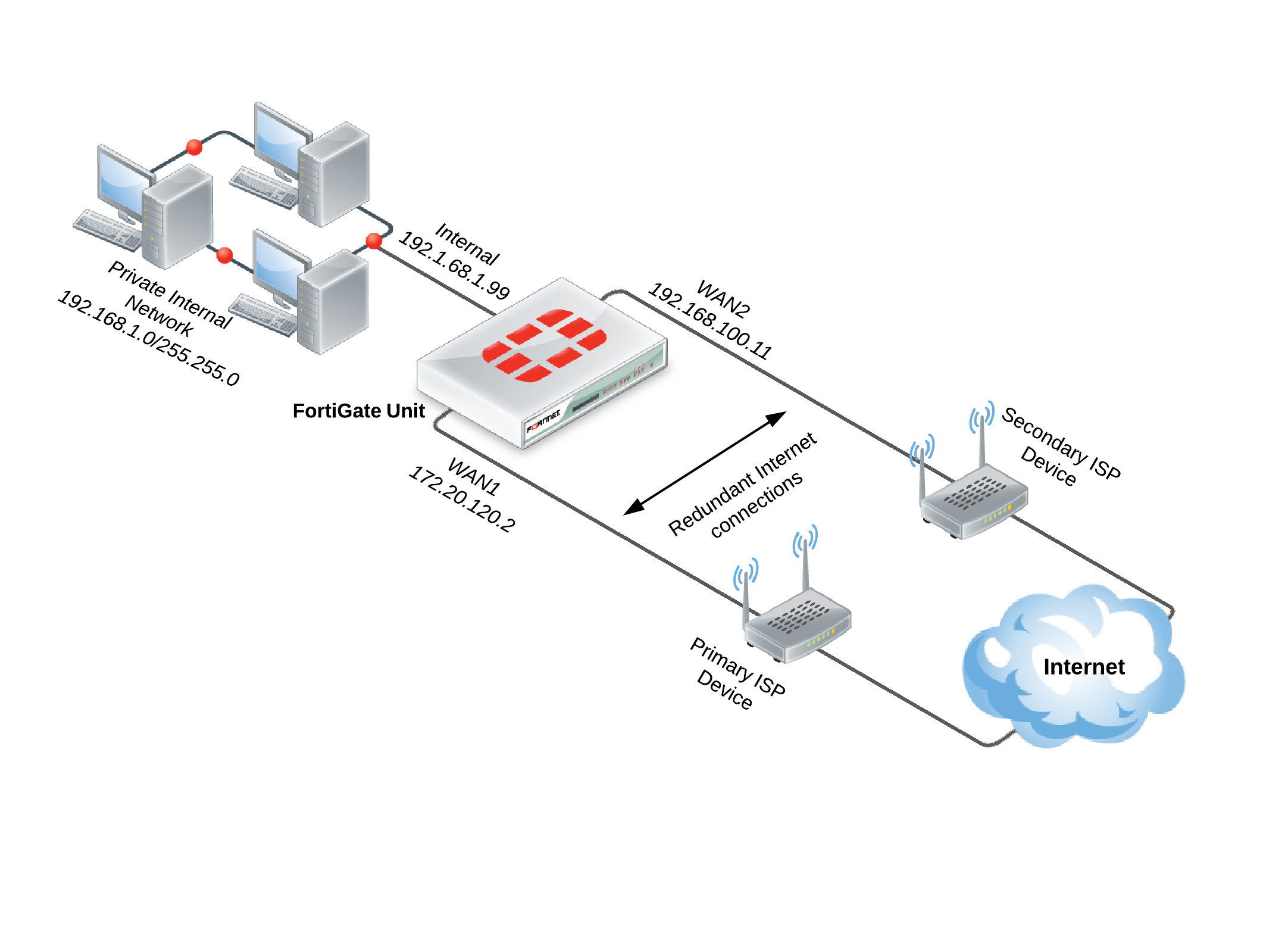
- Connect the FortiGate’s Internet-facing interfaces (typically WAN1 and WAN2) to your ISP-supplied equipment.
- Go to System > Network > WAN Link Load Balancing to create a WAN link interface, which is used to group multiple Internet connections together so that the FortiGate unit can treat them as a single interface.
| If you are using FortiOS 5.2.0, go to System > Network > Interfaces and select Create New > Virtual WAN to create a virtual WAN link (this feature was renamed WAN link interface in FortiOS 5.2.1). |
- Select an appropriate method of WAN Load Balancing from the following options:
- Source IP based – The next hop is based on the traffic’s source IP address.
- Weighted Round Robin – Weight is input for all the active members of the WAN link.
- Spill-over – A traffic cap is defined for active members; when it is exceeded, the traffic will automatically activate the standby link.
- Source-Destination IP based – The next hop is based on both the traffic’s source and destination IP address.
- Measured-Volume based – A volume ratio is set for each active member of the WAN link.
- Add your Internet-facing interfaces to the WAN link interface, configuring load balancing as required for each interface.
- Go to Router > Static > Static Routes and create a new default route. Set Device to the virtual WAN link.
- If your network uses IPv4 addresses, go to Policy & Objects > Policy > IPv4 and select Create New to add a security policy that allows users on the private network to access the Internet.
If your network uses IPv6 addresses, go to Policy & Objects > Policy > IPv6 and select Create New to add a security policy that allows users on the private network to access the Internet. If the IPv6 menu option is not available, go to System > Config > Features, turn on IPv6, and select Apply. For more information on IPv6 networks, see the IPv6 Handbook.
In the policy, set the Incoming Interface to the internal interface and the Outgoing Interface to the WAN link interface. You will also need to set Source Address, Destination Address, Schedule, and Service according to your network requirements. You can set these fields to the default all/ANY settings for now but should create the appropriate objects later after the policies have been verified. - Make sure the Action is set to ACCEPT. Turn on NAT and make sure Use Destination Interface Address is selected. Select OK.
| It is recommended to avoid using any security profiles, such as AntiVirus or web filtering, until after you have successfully installed the FortiGate unit. After the installation is verified, you can apply any required security profiles.
For more information about using security profiles, see the Security Profiles handbook. |
Results
Users on the internal network are now able to browse the Internet. They should also be able to connect to the Internet using any other protocol or connection method that you defined in the security policy.
The amount of traffic will use an individual member of the WAN link interface will depend on the load balancing method you selected. You can view this usage by going to System > FortiView > All Sessions and viewing the Dst Interface column. If this column is not shown, right-click on the title row and select Dst Interface from the dropdown menu. Scroll to the bottom of the menu and select Apply.
Installing a FortiGate in Transparent Mode
| Changing to Transparent mode removes most configuration changes made in NAT/Route mode. To keep your current NAT/Route mode configuration, backup the configuration using the System Information widget, found at System > Dashboard > Status. |
Network with a FortiGate unit in Transparent mode
![]()
- Before connecting the FortiGate unit to your network, go to System > Dashboard > Status and locate the System Information widget. Beside Operation Mode, select Change.
- Set the Operation Mode to Transparent. Set the Management IP/Netmask and Default Gateway to connect the FortiGate unit to the internal network. Select OK.
- Access the web-based manager by browsing to the new management IP.
- (Optional) The FortiGate unit’s DNS Settings are set to use FortiGuard DNS servers by default, which is sufficient for most networks. However, if you need to change the DNS servers, go to System > Network > DNS and add Primary and Secondary DNS servers. Select Apply.
- If your network uses IPv4 addresses, go to Policy & Objects > Policy > IPv4 and select Create New to add a security policy that allows users on the private network to access the Internet.
If your network uses IPv6 addresses, go to Policy & Objects > Policy > IPv6 and select Create New to add a security policy that allows users on the private network to access the Internet. If the IPv6 menu option is not available, go to System > Config > Features, turn on IPv6, and select Apply. For more information on IPv6 networks, see the IPv6 Handbook.
Set the Incoming Interface to the internal interface and the Outgoing Interface to the Internet-facing interface (typically WAN1). You will also need to set Source Address, Destination Address, Schedule, and Service according to your network requirements. You can set these fields to the default all/ANY settings for now but should create the appropriate objects later after the policies have been verified. - Make sure the Action is set to ACCEPT. Select OK.
| It is recommended to avoid using any security profiles, such as AntiVirus or web filtering, until after you have successfully installed the FortiGate unit. After the installation is verified, you can apply any required security profiles.
For more information about using security profiles, see the Security Profiles handbook. |
- Go to System > Dashboard > Status and locate the System Resources widget. Select Shutdown to power off the FortiGate unit.
Alternatively, you can also use the CLI commandexecute shutdown. - Connect the FortiGate unit between the internal network and the router.
- Connect the Internet-facing interface to the router’s internal interface and connect the internal network to the FortiGate using an internal port (typically port 1).
- Power on the FortiGate unit. You will experience downtime before the FortiGate unit starts up completely.
Results
Users on the internal network are now able to browse to the Internet. They should also be able to connect to the Internet using any other protocol or connection method that you defined in the security policy.
| If a FortiGate unit operating in Transparent mode is installed between your internet network and a server that is providing a network service to the internal network, such as DNS or DHCP, you must add a wan1-to-internal policy to allow the server’s response to flow through the FortiGate unit and reach the internal network. |
Troubleshooting your FortiGate Installation
If your FortiGate does not function as desired after completing the installation, try the following troubleshooting methods (those methods that are only applicable to one transparent mode are marked):
- Use FortiExplorer if you can’t connect to the FortiGate over Ethernet.
If you can’t connect to the FortiGate GUI or CLI, you may be able to connect using FortiExplorer. See your FortiGate unit’s QuickStart Guide for details. - Check for equipment issues.
Verify that all network equipment is powered on and operating as expected. Refer to the QuickStart Guide for information about connecting your FortiGate to the network. You will also find detailed information about the FortiGate unit LED indicators. - Check the physical network connections.
Check the cables used for all physical connections to ensure that they are fully connected and do not appear damaged, and make sure that each cable connects to the correct device and the correct Ethernet port on that device.
Also, check the Unit Operation widget, found at System > Dashboard > Status, to make sure the ports used in the connections are shown in green. - Verify that you can connect to the internal IP address of the FortiGate unit (NAT/Route mode).
Connect to the web-based manager from the FortiGate’s internal interface by browsing to its IP address. From the PC, try to ping the internal interface IP address; for example,ping 192.168.1.99.
If you cannot connect to the internal interface, verify the IP configuration of the PC. If you can ping the interface but can’t connect to the web-based manager, check the settings for administrative access on that interface. - Verify that you can connect to the management IP address of the FortiGate unit (Transparent mode).
From the internal network, attempt to ping the management IP address. If you cannot connect to the internal interface, verify the IP configuration of the PC and make sure the cables are connected and all switches and other devices on the network are powered on and operating. Go to the next step when you can connect to the internal interface. - Check the FortiGate interface configurations (NAT/Route mode).
Check the configuration of the FortiGate interface connected to the internal network, and check the configuration of the FortiGate interface that connects to the Internet to make sure Addressing Mode is set to the correct mode. - Verify the security policy configuration.
Go to Policy & Objects > Policy > IPv4 or Policy & Objects > Policy > IPv6 and verify that the internal interface to Internet-facing interface security policy has been added and is located near the top of the policy list. Check the Sessions column to ensure that traffic has been processed (if this column does not appear, right-click on the title row, select Sessions, and select Apply).
If you are using NAT/Route mode, check the configuration of the policy to make sure that NAT is turned on and that Use Destination Interface Address is selected. - Verify that you can connect to the Internet-facing interface’s IP address (NAT/Route mode).
Ping the IP address of the FortiGate’s Internet-facing interface. If you cannot connect to the interface, the FortiGate unit is not allowing sessions from the internal interface to Internet-facing interface. - Verify the static routing configuration (NAT/Route mode).
Go to Router > Static > Static Routes or System > Network > Routing and verify that the default route is correct. View the Routing Monitor (found either on the same page or at Router > Monitor > Routing Monitor) and verify that the default route appears in the list as a static route. Along with the default route, you should see two routes shown as Connected, one for each connected FortiGate interface. - Verify that you can connect to the gateway provided by your ISP.
Ping the default gateway IP address from a PC on the internal network. If you cannot reach the gateway, contact your ISP to verify that you are using the correct gateway. - Verify that you can communicate from the FortiGate unit to the Internet.
Access the FortiGate CLI and use the commandexecute ping8.8.8.8. You can also use theexecute traceroute 8.8.8.8command to troubleshoot connectivity to the Internet. - Verify the DNS configurations of the FortiGate unit and the PCs.
Check for DNS errors by pinging or using traceroute to connect to a domain name; for example:ping www.fortinet.com
If the name cannot be resolved, the FortiGate unit or PC cannot connect to a DNS server and you should confirm that the DNS server IP addresses are present and correct. - Confirm that the FortiGate unit can connect to the FortiGuard network.
Once registered, the FortiGate unit obtains antivirus and application control and other updates from the FortiGuard network. Once the FortiGate unit is on your network, you should confirm that it can reach the FortiGuard network.
First, check the License Information widget to make sure that the status of all FortiGuard services matches the services that you have purchased.
Go to System > Config > FortiGuard. Expand Web Filtering and Email Filtering Options and select Test Availability. After a minute, the web-based manager should indicate a successful connection. - Consider changing the MAC address of your external interface (NAT/Route mode).
Some ISPs do not want the MAC address of the device connecting to their network cable to change. If you have added a FortiGate unit to your network, you may have to change the MAC address of the Internet-facing interface using the following CLI command:
config system interface
edit <interface>
set macaddr <xx:xx:xx:xx:xx:xx>
end
end
- Check the FortiGate bridge table (Transparent mode).
When the FortiGate is in Transparent mode, the unit acts like a bridge sending all incoming traffic out on the other interfaces. The bridge is between interfaces on the FortiGate unit.
Each bridge listed is a link between interfaces. Where traffic is flowing between interfaces, you expect to find bridges listed. If you are having connectivity issues, and there are no bridges listed that is a likely cause. Check for the MAC address of the interface or device in question.
To list the existing bridge instances on the FortiGate unit, use the following CLI command:
diagnose netlink brctl name host root.b
show bridge control interface root.b host.
fdb: size=2048, used=25, num=25, depth=1
Bridge root.b host table
port no device devname mac addr ttl attributes
3 4 wan1 00:09:0f:cb:c2:77 88
3 4 wan1 00:26:2d:24:b7:d3 0
3 4 wan1 00:13:72:38:72:21 98
4 3 internal 00:1a:a0:2f:bc:c6 6
1 6 dmz 00:09:0f:dc:90:69 0 Local Static
3 4 wan1 c4:2c:03:0d:3a:38 81
3 4 wan1 00:09:0f:15:05:46 89
3 4 wan1 c4:2c:03:1d:1b:10 0
2 5 wan2 00:09:0f:dc:90:68 0 Local Static
If your device’s MAC address is not listed, the FortiGate unit cannot find the device on the network. This could indicate that the device is either not connected or not operating. Check the device’s network connections and make sure they are connected and operational.
- Either reset the FortiGate unit to factory defaults or contact the technical assistance center.
If all else fails, reset the FortiGate unit to factory defaults using the CLI commandexecute factoryreset. When prompted, typeyto confirm the reset.
| Resetting the FortiGate unit to factory defaults puts the unit back into NAT/Route mode. |
This information has been taken from Fortinet @
https://help.fortinet.com/fos50hlp/52data/Content/FortiOS/fortigate-getting-started-52/installation.htm