Step 1. Configure the management interface IP address and default route.
N5k-1(config)# int mgmt 0
N5k-1(config-if)# ip address 172.25.182.51/24
N5k-1(config-if)# vrf context management
N5k-1(config-vrf)# ip route 0.0.0.0/0 172.25.182.1
Step 2. Enable vPC and LACP.
N5k-1(config)# feature vpc
N5k-1(config)# feature lacp
Step 3. Create a VLAN.
N5k-1(config)#vlan 101
Step 4. Create the vPC domain.
N5k-1(config)# vpc domain 1
N5k-1(config)# vpc domain 1
Step 5. Configure the vPC role priority (optional).
N5k-1(config-vpc-domain)# role priority 1000
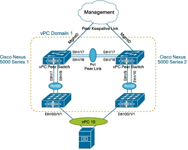
Step 6. Configure the peer keepalive link. The management interface IP address for Cisco Nexus 5000 Series Switch 2 is 172.25.182.52.
N5k-1(config-vpc-domain)# peer-keepalive destination 172.25.182.52
N5k-1(config-vpc-domain)# peer-switch
——–:: Management VRF will be used as the default VRF ::——–
Step 7. Configure the vPC peer link. Note that, as for a regular interswitch trunk, trunking must be turned on for the VLANs to which the vPC member port belongs.
N5k-1(config-vpc-domain)# int ethernet 1/17-18
N5k-1(config-if-range)# channel-group 1 mode active
N5k-1(config-if-range)# int po1
N5k-1(config-if)# vpc peer-link
N5k-1(config-if)# switchport mode trunk
N5k-1(config-if)# switchport trunk allowed vlan 1,101
Step 8. Configure the Cisco Nexus 2000 Series Fabric Extenders and the fabric interface.
N5k-1(config)# fex 100
N5k-1(config-fex)# pinning max-links 1
Change in Max-links will cause traffic disruption.
N5k-1(config-fex)# int e1/7-8
N5k-1(config-if-range)# channel-group 100
N5k-1(config-if-range)# int po100
N5k-1(config-if)# switchport mode fex-fabric
N5k-1(config-if)# fex associate 100
Step 9. Move the fabric extender interface to vPC. After fabric extender 100 (fex 100) comes online, create the PortChannel for interface eth100/1/1 and move the PortChannel to the vPC. Note that the PortChannel number and vPC number can be different, but the vPC number must be the same on both Cisco Nexus 5000 Series Switches.
N5k-1(config-if)# int ethernet 100/1/1
N5k-1(config-if)# channel-group 10
N5k-1(config-if)# int po10
N5k-1(config-if)# vpc 10
N5k-1(config-if)# switchport access vlan 101
The configuration steps for the second switch, Cisco Nexus 5000 Series Switch 2, are:
N5k-2(config)# int mgmt 0
N5k-2(config-if)# ip address 172.25.182.52/24
N5k-2(config-if)# vrf context management
N5k-2(config-vrf)# ip route 0.0.0.0/0 172.25.182.1
N5k-2(config)# feature vpc
N5k-2(config)# feature lacp
N5k-2(config)#vlan 101
N5k-2(config)# vpc domain 1
N5k-2(config-vpc-domain)# peer-keepalive destination 172.25.182.51
N5k-2(config-vpc-domain)# peer-switch
Note:
——–:: Management VRF will be used as the default VRF ::——–
N5k-2(config-vpc-domain)# int ethernet 1/17-18
N5k-2(config-if-range)# channel-group 1 mode active
N5k-2(config-if-range)# int po1
N5k-2(config-if)# vpc peer-link
N5k-2(config-if)# switchport mode trunk
N5k-2(config-if)# switchport trunk allowed vlan 1,101
N5k-2(config)# fex 100
N5k-2(config-fex)# pinning max-links 1
Change in Max-links will cause traffic disruption.
N5k-2(config-fex)# int e1/9-10
N5k-2(config-if-range)# channel-group 100
N5k-2(config-if-range)# int po100
N5k-2(config-if)# switchport mode fex-fabric
N5k-2(config-if)# fex associate 100
N5k-2(config-if)# int ethernet 100/1/1
N5k-2(config-if)# channel-group 10
N5k-2(config-if)# int po10
N5k-2(config-if)# vpc 10
N5k-2(config-if)# switchport access vlan 101