Understanding PIM
PIM is called protocol-independent: regardless of the unicast routing protocols used to populate the unicast routing table, PIM uses this information to perform multicast forwarding instead of maintaining a separate multicast routing table.
PIM is defined in RFC 2362, Protocol-Independent Multicast-Sparse Mode (PIM-SM): Protocol Specification. PIM is defined in these Internet Engineering Task Force (IETF) Internet drafts:
•Protocol Independent Multicast (PIM): Motivation and Architecture
•Protocol Independent Multicast (PIM), Dense Mode Protocol Specification
•Protocol Independent Multicast (PIM), Sparse Mode Protocol Specification
•draft-ietf-idmr-igmp-v2-06.txt, Internet Group Management Protocol, Version 2
•draft-ietf-pim-v2-dm-03.txt, PIM Version 2 Dense Mode
PIM Versions
PIMv2 includes these improvements over PIMv1:
•A single, active rendezvous point (RP) exists per multicast group, with multiple backup RPs. This single RP compares to multiple active RPs for the same group in PIMv1.
•A bootstrap router (BSR) provides a fault-tolerant, automated RP discovery and distribution mechanism that enables routers and multilayer switches to dynamically learn the group-to-RP mappings.
•Sparse mode and dense mode are properties of a group, as opposed to an interface. We strongly recommend sparse-dense mode, as opposed to either sparse mode or dense mode only.
•PIM join and prune messages have more flexible encoding for multiple address families.
•A more flexible hello packet format replaces the query packet to encode current and future capability options.
•Register messages to an RP specify whether they are sent by a border router or a designated router.
•PIM packets are no longer inside IGMP packets; they are standalone packets.
PIM DM builds source-based multicast distribution trees. In dense mode, a PIM DM router or multilayer switch assumes that all other routers or multilayer switches forward multicast packets for a group. If a PIM DM device receives a multicast packet and has no directly connected members or PIM neighbors present, a prune message is sent back to the source to stop unwanted multicast traffic. Subsequent multicast packets are not flooded to this router or switch on this pruned branch because branches without receivers are pruned from the distribution tree, leaving only branches that contain receivers.
When a new receiver on a previously pruned branch of the tree joins a multicast group, the PIM DM device detects the new receiver and immediately sends a graft message up the distribution tree toward the source. When the upstream PIM DM device receives the graft message, it immediately puts the interface on which the graft was received into the forwarding state so that the multicast traffic begins flowing to the receiver.
PIM-SM uses shared trees and shortest-path-trees (SPTs) to distribute multicast traffic to multicast receivers in the network. In PIM-SM, a router or multilayer switch assumes that other routers or switches do not forward multicast packets for a group, unless there is an explicit request for the traffic (join message). When a host joins a multicast group using IGMP, its directly connected PIM-SM device sends PIM join messages toward the root, also known as the RP. This join message travels router-by-router toward the root, constructing a branch of the shared tree as it goes.
The RP keeps track of multicast receivers. It also registers sources through register messages received from the source’s first-hop router (designated router [DR]) to complete the shared tree path from the source to the receiver. When using a shared tree, sources must send their traffic to the RP so that the traffic reaches all receivers.
Prune messages are sent up the distribution tree to prune multicast group traffic. This action permits branches of the shared tree or SPT that were created with explicit join messages to be torn down when they are no longer needed.
When the number of PIM-enabled interfaces exceeds the hardware capacity and PIM-SM is enabled with the SPT threshold is set to infinity, the switch does not create (S,G) entries in the multicast routing table for the some directly connected interfaces if they are not already in the table. The switch might not correctly forward traffic from these interfaces.
The PIM stub routing feature, available in all software images, reduces resource usage by moving routed traffic closer to the end user.
Multicast Distribution Trees
Multicast-capable routers create distribution trees that control the path that IP multicast traffic takes through the network in order to deliver traffic to all receivers. The two basic types of multicast distribution trees are source trees and shared trees, which are described in the following sections.
Source Trees
The simplest form of a multicast distribution tree is a source tree with its root at the source and branches forming a spanning tree through the network to the receivers. Because this tree uses the shortest path through the network, it is also referred to as a shortest path tree (SPT).
Figure 11 shows an example of an SPT for group 224.1.1.1 rooted at the source, Host A, and connecting two receivers, Hosts B and C.
Figure 11 Host A Source Tree

The special notation of (S, G), pronounced “S comma G,” enumerates an SPT where S is the IP address of the source and G is the multicast group address. Using this notation, the SPT for the example shown inFigure 11 would be (192.168.1.1, 224.1.1.1).
The (S, G) notation implies that a separate SPT exists for each individual source sending to each group—which is correct. For example, if Host B is also sending traffic to group 224.1.1.1 and Hosts A and C are receivers, a separate (S, G) SPT would exist with a notation of (192.168.2.2, 224.1.1.1).
Shared Trees
Unlike source trees that have their root at the source, shared trees use a single common root placed at some chosen point in the network. This shared root is called a rendezvous point (RP).
Figure 12 shows a shared tree for the group 224.2.2.2 with the root located at Router D. This shared tree is unidirectional. Source traffic is sent towards the RP on a source tree. The traffic is then forwarded down the shared tree from the RP to reach all of the receivers (unless the receiver is located between the source and the RP, in which case it will be serviced directly).
Figure 12 Shared Distribution Tree
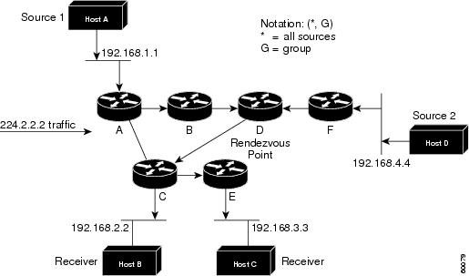
In this example, multicast traffic from the sources, Hosts A and D, travels to the root (Router D) and then down the shared tree to the two receivers, Hosts B and C. Because all sources in the multicast group use a common shared tree, a wildcard notation written as (*, G), pronounced “star comma G,” represents the tree. In this case, * means all sources, and G represents the multicast group. Therefore, the shared tree shown inFigure 12 would be written as (*, 224.2.2.2).
Source Trees Versus Shared Trees
Both source trees and shared trees are loop-free. Messages are replicated only where the tree branches.
Members of multicast groups can join or leave at any time; therefore the distribution trees must be dynamically updated. When all the active receivers on a particular branch stop requesting the traffic for a particular multicast group, the routers prune that branch from the distribution tree and stop forwarding traffic down that branch. If one receiver on that branch becomes active and requests the multicast traffic, the router will dynamically modify the distribution tree and start forwarding traffic again.
Source trees have the advantage of creating the optimal path between the source and the receivers. This advantage guarantees the minimum amount of network latency for forwarding multicast traffic. However, this optimization comes at a cost: The routers must maintain path information for each source. In a network that has thousands of sources and thousands of groups, this overhead can quickly become a resource issue on the routers. Memory consumption from the size of the multicast routing table is a factor that network designers must take into consideration.
Shared trees have the advantage of requiring the minimum amount of state in each router. This advantage lowers the overall memory requirements for a network that only allows shared trees. The disadvantage of shared trees is that under certain circumstances the paths between the source and receivers might not be the optimal paths, which might introduce some latency in packet delivery. For example, in Figure 12, the shortest path between Host A (source 1) and Host B (a receiver) would be Router A and Router C. Because we are using Router D as the root for a shared tree, the traffic must traverse Routers A, B, D and then C. Network designers must carefully consider the placement of the rendezvous point (RP) when implementing a shared tree-only environment.
Reverse Path Forwarding (RPF)
PIM uses the unicast routing information to create a distribution tree along the reverse path from the receivers towards the source. The multicast routers then forward packets along the distribution tree from the source to the receivers. RPF is a key concept in multicast forwarding. It enables routers to correctly forward multicast traffic down the distribution tree. RPF makes use of the existing unicast routing table to determine the upstream and downstream neighbors. A router will forward a multicast packet only if it is received on the upstream interface. This RPF check helps to guarantee that the distribution tree will be loop-free.
RPF Check
When a multicast packet arrives at a router, the router performs an RPF check on the packet. If the RPF check succeeds, the packet is forwarded. Otherwise, it is dropped.
For traffic flowing down a source tree, the RPF check procedure works as follows:
1. ![]() The router looks up the source address in the unicast routing table to determine if the packet has arrived on the interface that is on the reverse path back to the source.
The router looks up the source address in the unicast routing table to determine if the packet has arrived on the interface that is on the reverse path back to the source.
2. ![]() If the packet has arrived on the interface leading back to the source, the RPF check succeeds and the packet is forwarded.
If the packet has arrived on the interface leading back to the source, the RPF check succeeds and the packet is forwarded.
3. ![]() If the RPF check in Step 2 fails, the packet is dropped.
If the RPF check in Step 2 fails, the packet is dropped.
Figure 13 shows an example of an unsuccessful RPF check.
Figure 13 RPF Check Fails
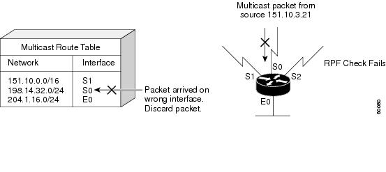
As Figure 13 illustrates, a multicast packet from source 151.10.3.21 is received on serial interface 0 (S0). A check of the unicast route table shows that S1 is the interface this router would use to forward unicast data to 151.10.3.21. Because the packet has arrived on interface S0, the packet is discarded.
Figure 14 shows an example of a successful RPF check.
Figure 14 RPF Check Succeeds
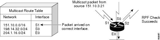
In this example, the multicast packet has arrived on interface S1. The router refers to the unicast routing table and finds that S1 is the correct interface. The RPF check passes, and the packet is forwarded.
Protocol Independent Multicast (PIM)
PIM is IP routing protocol-independent and can leverage whichever unicast routing protocols are used to populate the unicast routing table, including Enhanced Interior Gateway Routing Protocol (EIGRP), Open Shortest Path First (OSPF), Border Gateway Protocol (BGP), and static routes. PIM uses this unicast routing information to perform the multicast forwarding function. Although PIM is called a multicast routing protocol, it actually uses the unicast routing table to perform the RPF check function instead of building up a completely independent multicast routing table. Unlike other routing protocols, PIM does not send and receive routing updates between routers.
PIM forwarding modes are described in the following sections:
•![]() PIM Dense Mode (PIM-DM)
PIM Dense Mode (PIM-DM)
•![]() PIM Sparse Mode (PIM-SM)
PIM Sparse Mode (PIM-SM)
•![]() Bidirectional PIM (Bidir-PIM)
Bidirectional PIM (Bidir-PIM)
PIM Dense Mode (PIM-DM)
PIM-DM uses a push model to flood multicast traffic to every corner of the network. This push model is a brute force method for delivering data to the receivers. This method would be efficient in certain deployments in which there are active receivers on every subnet in the network.
PIM-DM initially floods multicast traffic throughout the network. Routers that have no downstream neighbors prune back the unwanted traffic. This process repeats every 3 minutes.
Routers accumulate state information by receiving data streams through the flood and prune mechanism. These data streams contain the source and group information so that downstream routers can build up their multicast forwarding table. PIM-DM supports only source trees—that is, (S, G) entries—and cannot be used to build a shared distribution tree.
PIM Sparse Mode (PIM-SM)
PIM-SM uses a pull model to deliver multicast traffic. Only network segments with active receivers that have explicitly requested the data will receive the traffic.
PIM-SM distributes information about active sources by forwarding data packets on the shared tree. Because PIM-SM uses shared trees (at least, initially), it requires the use of a rendezvous point (RP). The RP must be administratively configured in the network.
Sources register with the RP and then data is forwarded down the shared tree to the receivers. The edge routers learn about a particular source when they receive data packets on the shared tree from that source through the RP. The edge router then sends PIM (S, G) join messages towards that source. Each router along the reverse path compares the unicast routing metric of the RP address to the metric of the source address. If the metric for the source address is better, it will forward a PIM (S, G) join message towards the source. If the metric for the RP is the same or better, then the PIM (S, G) join message will be sent in the same direction as the RP. In this case, the shared tree and the source tree would be considered congruent.
Figure 15 shows a standard PIM-SM unidirectional shared tree. The router closest to the source registers with the RP (part A in Figure 15)and then creates a source tree (S, G) between the source and the RP (part B in Figure 15). Data is forwarded down the shared tree (*, G) towards the receiver from the RP.
Figure 15 Unidirectional Shared Tree and Source Tree
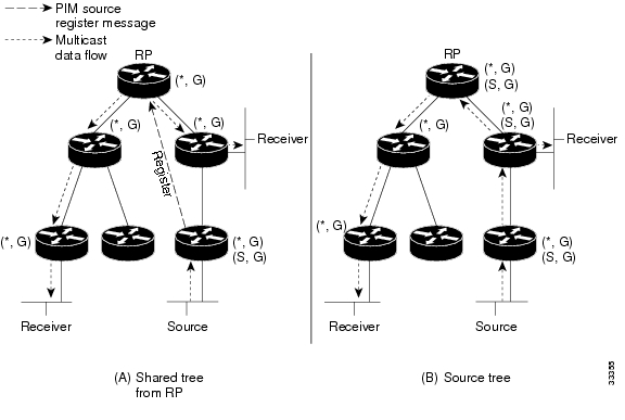
If the shared tree is not an optimal path between the source and the receiver, the routers dynamically create a source tree and stop traffic from flowing down the shared tree. This behavior is the default behavior in Cisco IOS software. Network administrators can force traffic to stay on the shared tree by using the Cisco IOS ip pim spt-threshold infinity command.
PIM-SM was originally described in RFC 2362, Protocol Independent Multicast-Sparse Mode (PIM-SM): Protocol Specification. This RFC is being revised and is currently in draft form. The draft specification,Protocol Independent Multicast-Sparse Mode (PIM-SM): Protocol Specification (Revised), can be found on the IETF website (http://www.ietf.org).
PIM-SM scales well to a network of any size, including those with WAN links. The explicit join mechanism will prevent unwanted traffic from flooding the WAN links.
Bidirectional PIM (Bidir-PIM)
Bidirectional PIM (bidir-PIM) is an enhancement of the PIM protocol that was designed for efficient many-to-many communications within an individual PIM domain. Multicast groups in bidirectional mode can scale to an arbitrary number of sources with only a minimal amount of additional overhead.
The shared trees that are created in PIM Sparse Mode are unidirectional. This means that a source tree must be created to bring the data stream to the RP (the root of the shared tree) and then it can be forwarded down the branches to the receivers. Source data cannot flow up the shared tree toward the RP—this would be considered a bidirectional shared tree.
In bidirectional mode, traffic is routed only along a bidirectional shared tree that is rooted at the RP for the group. In bidir-PIM, the IP address of the RP acts as the key to having all routers establish a loop-free spanning tree topology rooted in that IP address. This IP address need not be a router address, but can be any unassigned IP address on a network that is reachable throughout the PIM domain.
Figure 16 shows a bidirectional shared tree. Data from the source can flow up the shared tree (*, G) towards the RP and then down the shared tree to the receiver. There is no registration process and so source tree (S, G) is created.
Figure 16 Bidirectional Shared Trees

Bidir-PIM is derived from the mechanisms of PIM sparse mode (PIM-SM) and shares many of the shared tree operations. Bidir-PIM also has unconditional forwarding of source traffic toward the RP upstream on the shared tree, but no registering process for sources as in PIM-SM. These modifications are necessary and sufficient to allow forwarding of traffic in all routers solely based on the (*, G) multicast routing entries. This feature eliminates any source-specific state and allows scaling capability to an arbitrary number of sources.
The current specification of bidir-PIM can be found in the IETF draft titled Bi-directional Protocol Independent Multicast (BIDIR-PIM) on the IETF website (http://www.ietf.org).
Pragmatic General Multicast (PGM)
PGM is a reliable multicast transport protocol for applications that require ordered, duplicate-free, multicast data delivery from multiple sources to multiple receivers. PGM guarantees that a receiver in a multicast group either receives all data packets from transmissions and retransmissions or can detect unrecoverable data packet loss.
The PGM reliable transport protocol is implemented on the sources and on the receivers. The source maintains a transmit window of outgoing data packets and will resend individual packets when it receives a negative acknowledgment (NAK). The network elements (such as routers) assist in suppressing an implosion of NAKs (when a data packet is dropped) and in efficient forwarding of the re-sent data only to the networks that need it.
PGM is intended as a solution for multicast applications with basic reliability requirements. PGM is better than best effort delivery but not 100% reliable. The specification for PGM is network layer-independent. The Cisco implementation of the PGM Router Assist feature supports PGM over IP.
You can find the current specification for PGM in RFC 3208, PGM Reliable Transport Protocol Specification.

Note ![]() You can find all RFCs and Internet Engineering Task Force (IETF) drafts on the IETF website (http://www.ietf.org).
You can find all RFCs and Internet Engineering Task Force (IETF) drafts on the IETF website (http://www.ietf.org).
Interdomain Multicast Protocols
The following topics represent interdomain multicast protocols—meaning, protocols that are used between multicast domains. These protocols are also used by ISPs to forward multicast traffic on the Internet. The following protocols are discussed in this section:
•![]() Multiprotocol Border Gateway Protocol (MBGP)
Multiprotocol Border Gateway Protocol (MBGP)
•![]() Multicast Source Discovery Protocol (MSDP)
Multicast Source Discovery Protocol (MSDP)
•![]() Source Specific Multicast (SSM)
Source Specific Multicast (SSM)
Multiprotocol Border Gateway Protocol (MBGP)
MBGP provides a method for providers to distinguish which route prefixes they will use for performing multicast RPF checks. The RPF check is the fundamental mechanism that routers use to determine the paths that multicast forwarding trees will follow and to successfully deliver multicast content from sources to receivers. For more information, see the “Reverse Path Forwarding (RPF)” section earlier in this document.
MBGP is described in RFC 2283, Multiprotocol Extensions for BGP-4. Because MBGP is an extension of BGP, it contains the administrative machinery that providers and customers require in their interdomain routing environment, including all the inter-AS tools to filter and control routing (for example, route maps). Therefore, any network utilizing internal BGP (iBGP) or external BGP (eBGP) can use MBGP to apply the multiple policy control knobs familiar in BGP to specify the routing policy (and thereby the forwarding policy) for multicast.
Two path attributes, MP_REACH_NLRI and MP_UNREACH_NLRI, were introduced in BGP4. These new attributes create a simple way to carry two sets of routing information—one for unicast routing and one for multicast routing. The routes associated with multicast routing are used for RPF checking at the interdomain borders.
The main advantage of MBGP is that an internetwork can support noncongruent unicast and multicast topologies. When the unicast and multicast topologies are congruent, MBGP can support different policies for each. Separate BGP routing tables are maintained for the Unicast Routing Information Base (U-RIB) and the Multicast Routing Information Base (M-RIB). The M-RIB is derived from the unicast routing table with the multicast policies applied. RPF checks and PIM forwarding events are performed based on the information in the M-RIB. MBGP provides a scalable policy-based interdomain routing protocol.
and more to come because i dont understand the whole thing concept … i know the command but the why ! i dont know yet so more to come .